Section 3: Metal-detector search procedures
3.1 General
See Section 2: Metal-detector set-up before reading this.
What follows are basic procedures for use with all the current models of metal-detector that I know. It is intended to provide a basis that you can edit and refine to suit your equipment and working preferences.
The Metal-detector search procedure results in 'metal-free'” ground subject to the ability and settings of the model of metal-detector in use. When there are no minimum-metal threats in an area, the metal-detector may be 'tuned'" so that it does not signal on very small metal pieces. As long as the detector is set-up appropriately to find the anticipated hazards at the Task, the metal-detector search and clearance procedure constitutes 'clearance' as defined in the IMAS.
Internal QA shall be conducted by a supervisor on each deminer ’s working area at least once in each working day. At least 50% of the area worked should be checked, and any clear and unambiguous detector indications shall be interpreted as a nonconformity such that the entire area worked by that deminer since the last QA check shall be re-searched and the deminer subjected to appropriate correction/discipline.
External QA may be conducted with the same metal-detectors calibrated/adjusted in the same way. The use of another model of metal-detector or metal-detectors calibrated/adjusted in another way does not automatically represent valid external QA or QC. QA/C staff can check the area with other detectors and other settings, but finding metal will not then constitute a non-conformity such that search must be repeated. Finding a mine would constitute a critical non-conformity because it would show that the detector in use (as configured) was not capable of reliably finding the hazards.
Any metal-detector that performs erratically or fails to perform acceptably must be withdrawn from service immediately.
When conducting metal-detector search and clearance, no one metre wide lane should exceed five metres in length. When it reaches five metres, the lane should be closed and an adjacent lane cut. When the second lane reaches five metres, it can continue a further five metres before being closed and the deminer returns to extend the first lane. The process is intended to ensure easy CASEVAC access by limiting the length of any one metre wide lane down which a stretcher might have to be carried. Variations to this requirement must be authorised by the Site Supervisor and recorded with reasons (usually in the Site Log).
3.2 Metal-detector search and clearance requirements
Only deminers internally trained and certificated to use the specific model of detector can be used to perform metal-detector search procedures with that detector.
Generally a metal-detector search procedure should not be used at the same Task as excavation clearance procedures (to avoid complex marking of which areas have been processed in which ways). However, the procedures may be mixed as long as the areas searched with the detectors are clearly marked and readily distinguishable from areas processed in other ways. This may, for example, occur when breaches are cut with metal-detectors and mine belts processed by area-excavation (or vice versa).
In all cases, the detector’s ability (after Ground Compensation) to locate the anticipated target in the actual ground conditions at the site must be checked before any decision to use metal-detector search can be taken. During use, the detector’s ability to locate the target will be checked every time the detector is switched on, every hour of continuous use, or more frequently. [This is required because metal-detector settings can 'drift' over time.] This check must be made by the deminer using the detector, so checking his/her ability to use the detector as well as the performance of the detector itself.
Metal-free detector 'Calibration areas' and detector 'Test areas' will be established at the site, and should be moved forward as the cleared area advances to give confidence that the calibration and tests are always taking place in the ground conditions that prevail where the metal-detector is actually being used.
Whichever model of detector is used, the required rate of advance is one half of the search head width, or less, unless the procedure documented under Section 2.4 Determining the area interrogated under a search-head in the Metal-detector set-up section has been followed and a different search-head advance determined.
3.3 Sweeping the detector search-head
Metal-detectors use a movement principle that is either 'static' or 'dynamic' (and a few models can be switched between both). A static detector will continue to signal when the search-head is held stationary over a target. A dynamic detector will only signal when the search-head is moving. It is essential that deminers have been trained for long enough for the correct movement of the search-head to have become habitual before they are moved from a training area to a real Task site.
The following procedure presumes that the undergrowth in the search area has been cut close to the ground surface. This procedure achieves a one third overlap of a small 24cm long search-head, and should be varied when search-heads of a significantly different size are used. The search-head should be moved so that it is always close to the ground surface without touching it. The detector search-head must NEVER be brushed along the ground or used to "pat" the ground with an up-and-down movement.
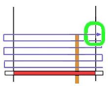
1) Either, a 50cm long flat wooden 'Guide-stick'" is laid so that is extends forward of the Base-stick (experienced deminers may dispense with the Guide-stick)...

or a second stick is placed 50cm in front of the first - so "boxing" the area to be searched.

2) The detector-head is placed in the middle of the Base-stick, with at least one third of the head behind the Base-stick.

3) The detector head is moved to the right and beyond the end of the Base-stick. The overlap outside the lane must be at least 10cm. The search-head is constantly kept as close to the ground as possible without applying pressure to the ground.

4) The detector-head is moved all the way to the left without advancing it and beyond the end of the Base-stick. The overlap outside the lane must be at least 10cm.

5) The detector-head is moved forward by a third of the search-head length or less, and swept to the right. If the detector signals, the sweeps are not interrupted.

6) Advancing by one third of a search-head length or less, the head is advanced until it is at least one-third over the end of the measuring stick and over the nominal side of the search area (overlap). If the detector signals, the sweeps are not interrupted.
7) The detector head is moved back over the search area in a reverse action. If the detector signals, the sweeps are not interrupted, but a mental map of the search area is made.

The deminer now knows how many signals are in the area and their approximate position. If two signals are close together, or are in a linear pattern (as is common with lengths of wire), he/she knows this and so can pinpoint the closest signal (or the part of a signal-source that is closest).
8) If there are signals in the area, the deminer should first inspect the ground visually for surface metal and carefully remove any obvious metal by hand. Exposed barbed wire or other items must not be pulled if parts are under the ground. After a visual inspection, the deminer may use a magnetic tool to try to remove metal that cannot be easily seen.
3.4 Using magnet tools to reduce fragmentation
Metal fragmentation can be extensive and can slow down the process of metal-detector search dramatically. Generally the fragments result from human activity or are unintended battle-scrap. Many are on (or close to) the ground surface. To remove these, powerful neodymium magnets can be used to attract ferrous material and so reduce the number of signal-investigations that have to be made.
NOTE: In very moist ground conditions, the use of magnets may be ineffective and so omitted. If there is a well-founded fear of magnetic-influence fuzes in the area, the use of a magnet must be omitted.
3.4.1 Magnet attached to trowel
Use of a magnet-trowel should be restricted if the Threat assessment at the Task indicates the possible presence of particularly sensitive devices.
A magnet-clip is attached to the blade of a trowel. The clip has magnets on both sides and is held to the trowel blade by the magnets being attracted to each other.

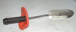
The trowel is passed over the ground above the signal indication.

Surface fragments are attracted to the magnet and can often be heard 'clacking' onto it.

When the Threat assessment has not identified a hazard from especially sensitive devices (or devices in an unstable condition) the magnet can be used to touch the ground lightly and to scrape raised soil on uneven ground.
When uneven ground is lightly scraped, the spoil is tipped over the magnet and off the trowel. Ferrous fragments stick to the magnet as they pass.


The trowel must not be used to dig down or apply downward pressure during the fragment-removal procedure.
After using the magnet-trowel, the area must be searched with the detector again as described in Section 3.3. This must be done whether or not fragments have been found because the action of the trowel may have moved the signals around. Not all metal is ferrous, and non-ferrous metal will not be attracted to the magnet.
3.4.2 Magnet attached to Brush-rake
When the Threat assessment has not identified a hazard from especially sensitive devices (or devices in an unstable condition) the Brush-rake magnet can be used to rake the area in which a metal-detector has signalled. This procedure can only be used AFTER the Brush rake has been tested to ensure that it does not readily initiate any of the anticipated hazards.
Testing the Brush-rake involves using the rake to expose a rendered-safe target-mine in the ground conditions pertaining at the Task. The target-mine must be an example of the most sensitive anticipated threat in the Task area. The initiation mechanism must be intact and the High Explosive removed. The target-mine is concealed and a deminer wearing visor and frontal protection must attempt to expose the mine with the Brush-rake. If the Brush rake initiates the mechanism in the target-mine, the Brush-rake cannot be used where those threats are anticipated.
The Brush-rake (sometimes known as a leaf-rake) has a strip of neodymium magnets attached to its underside. The rake head is angled to the rake-handle so that the magnet-strip brushes the ground as the rake is used.
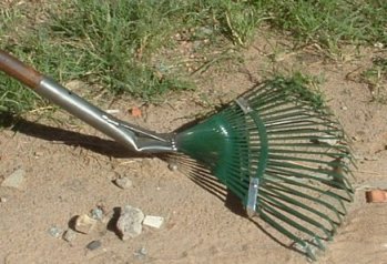
In a standing position, and holding the handle well back from the rake-head, the deminer rakes over the area where the metal-detector signaled.
The rake tines scratch the ground surface and can help to loosen fragments just below the ground surface, which are then attracted to the magnet strip


After using the Brush-rake magnet, the area must be searched with the detector again as described in Section 3.3. This must be done whether or not fragments have been found because the action of the rake may have moved the signals around. Not all metal is ferrous, and non-ferrous metal will not be attracted to the magnet.
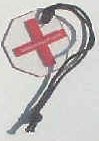
3.5 Placing a Nearest-point Target-marker
The marker can be a small piece of wood or stone, painted red. When available, thin polycarbonate markers are preferred because they are so thin that they do not prevent the detector search-head being moved over them to confirm their position after placement. The nylon cord allows it to be picked up safely.
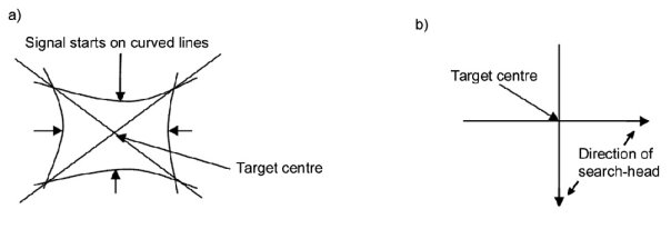
After the area has been searched with the metal-detector, surface fragments removed and the search repeated, the deminer must pinpoint the closest signal to the Base-stick and place a marker. The method of pinpointing varies with the metal-detector but will either involve using the search-head to approach the signal from all sides ("a" below) or moving the search head across the signal in 'cross-hairs' ("b" below). When a small target is deeply buried, it may not be possible to pinpoint accurately, so the deminer should err on the side of caution and place the marker slightly closer to the base-stick than might be necessary.
The marker is placed at the nearest part of the signal to the deminer's Base-stick.
Target-markers are sometimes called Centre-markers and sometimes Nearest-point markers. When dealing with plastic cased mines, they often mark the same place - which is the centre of the mine.

In this case, a Nearest-point marker actually indicates the centre of the plastic-cased AT mine because that is where the metal content is.

And in this case, a Centre marker indicates the centre of the plastic-cased AP mine.
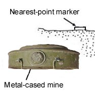
When the target mine has a metal case, the signal may be extensive and the Nearest-point marker will be placed at the place closest to the deminer where the signal starts.
Other mines can give more than one signal because the metal parts are spread inside them.
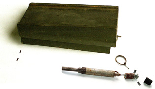
This picture shows the metal content of a PMD-6 alongside the complete wooden-cased mine. The hinge-pins on the left often give a separate signal from the MUV fuze. Some detectors may signal especially loudly on the piece of lead that has been cut in half by the arming delay mechanism on the right. Experienced deminers who know they are looking for PMD-6 mines can often tell which way around the mine is in the ground because of the signal pattern.
If the marker were placed at the Centre of the reading, the deminer could start to investigate the reading by digging directly onto the top of the mine. For this reason, the marker is always placed at the Nearest point of any metal-detector signal.
When the nearest signal has been pinpointed, either 1) or 2) below are used:
1) hand-tool signal investigation procedure
2) combined detector/rake investigation procedure.
See Investigating a metal-detector reading for these procedures.
HOME
